150 Watt Amplifier Circuit
Low Cost 150 Watt Amplifier Circuit
Description
This is the cheapest 150 Watt amplifier circuit you can get,I think.Based on two Darlington power transistors TIP 142 and TIP 147 ,this circuit can deliver a blasting 150 W Rms to a 4 Ohm speaker.Enough for you to get rocked?,then try out this.
TIP 147 and 142 are complementary Darlington pair transistors which can handle 5 A current and 100V ,famous for their ruggedness. Here two BC 558 transistorsQ5 and Q6 are wired as pre amplifier and TIP 142 ,TIP 147 together with TIP42 (Q1,Q2,Q3) for driving the speaker.This circuit is designed so rugged that this can be assembled even on a perf board or even by pin to pin soldering.The circuit can be powered from a +/-45V 5A dual power supply.You must try this circuit.Its working great.
The preamplifier section of this circuit is based around Q4 and Q5 which forms a differential amplifier. The use of a differential amplifier in the input stage reduces noise and also provides a means for applying negative feedback. Thus overall performance of the amplifier is improved. Input signal is applied to the base of Q5 through the DC decoupling capacitor C2. Feedback voltage is applied to the base of Q4 from the junction of 0.33 ohm resistors through the 22K resistor. A complementary Class AB push-pull stage is built around the transistors Q1 and Q2 for driving the loud speaker. Diodes D1 and D2 biases the complementary pair and ensures Class AB operation. Transistor Q3 drives the push-pull pair and its base is directly coupled to the collector of Q5.
Circuit Diagram & Parts List .
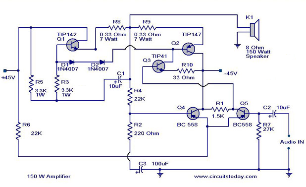
150 watt amplifier circuit diagram
Notes.
- Remember TIP 142 and 147 are Darlington pairs .They are shown as conventional transistors in figure for ease.So don’t get confused.Even though each of them have 2 transistors ,2 resistors and 1 diode inside ,only three pins ,base emitter and collector are coming out.Rest are connected internally.So its quite OK to assume each of them as transistor for ease.
- Use a well regulated and filtered power supply.
- Connect a 10K POT in series with the input as volume control if you need.Not shown in circuit diagram.
Power supply for this circuit.
A +40/-40 unregulated dual supply for powering this amplifier project is shown below. This power supply is only enough for powering one channel and for stereo applications double the current ratings of the transformer, diodes and fuses.
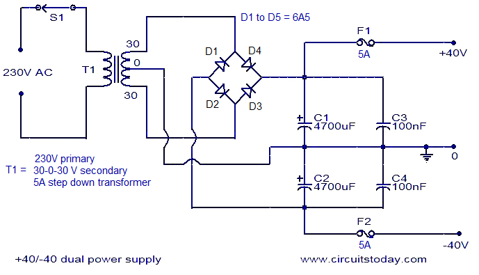
Power supply for this project
Internal diagram and pin out.
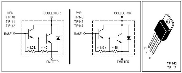
TIP 142-TIP 147 Pin Out Diagram with Schematics
Written by Admin
ChromeGT is a modern, powerful and professional Blogger template made for your Portfolio, Business or almost any other kind of website.
0 comments: